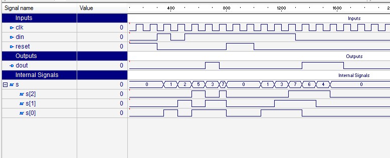
Serial 2 S Complementer Shift Register

Recently, I was going through the pile of old projects which I had made when I had just got into electronics. I found a 24 x 6 LED matrix which was my first 'complete' project. A lot of messy wiring, not perfect but it still works fine. At the time I made this project, I never thought about the components which were used, how did they work, etc. I just wanted to complete it as soon as possible and have some fun. And I'm sure there are many like me. One such component used in the LED matrix was 74HC595 which is a Shift Register.
Yet another popular device which is used when you run out of output pins. There are 24 columns which need to be controlled individually which means that you need 24 output pins on the Arduino (or any other microcontroller) which is a lot and makes the wiring messy. That is why shift registers are used. Now we can control 24 rows (or more) by using just 5 pins on the Arduino.
6-10) Design a serial 2’s complementer with shift register and a flip-flop. See solution for Problem 5-7 Page: 3. The binary number is shifted out from one side and it’s 2’s complement shifted into the other side of the shift register. The counter may not operate properly.
Clever, isn't it? In my previous, I made an LCD Trainer Kit which won a First Prize in Contest. It got some lovely comments from the people which suggests that the idea of getting back to basics is great. In this Instructable, let us look at the working of a shift register and at the end build a small kit to see shift register in action. Let's get back to basics!
The shift register we will be using is 74HC595 which is an 8-bit Tri-state Shift Register i.e. With 8 outputs. Tri (3) states mean that the output can be set to either HIGH, LOW or High Impedance.
Let us have a look at the pins of the IC and their function. Note: Rising Edge - Transition from 0V to 5V (LOW to HIGH) Falling Edge - Transition from 5V to 0V (HIGH to LOW) Inputs (Control Pins) Pin 14 - Serial Data In Data is fed into the register from this pin.
Free download buku ariel kisah lainnya noah band. Currently It supports 55 formats of video downloads. GenYoutube provides Youtube video downloads in mp4, webm, m4a, 3gp and 3D formats which ranges from mobile friendly to HDTV resolution. Now you can download songs, movies, episodes, trailers, clips or any Youtube video without visitng the Youtube site with hassle free controls and beautiful responsive UI.
Serial means data is fed in bit by bit. Pin 13 - Output Enable (OE) This pin turns the output ON or OFF.
It is an active low pin meaning that pulling the pin LOW enables the output. We will be connecting it directly to GND to make the output always ON. Pin 12 - Storage Register Clock (RCLK) When this pin is pulled HIGH, the data from the storage register is transferred to the output. Pin 11 - Shift Register Clock (SRCLK) A clock signal is provided to this pin. The data from Pin 14 (Serial Data In) is registered only at the rising edge of the clock. In simple words, when the clock signal rises from 0V to 5V, only then the data present at Pin 14 gets stored in the register.
Pin 10 - Shift Register Clear (SRCLR) It is an active low pin. As the name suggests, when this pin is pulled LOW, it clears all the data from the storage register.

We will be connecting it to 5V permanently so that the data is never cleared from the storage register. Output Pin 15, Pin 1 to 7 - QA to QH These are the 8 outputs of the shift register. Let's get this thing running. We will try to light up LEDs at Q0 and Q1 i.e. 0000 0011 Note: Pushing the button makes that particular pin HIGH (or 1) and l eaving the button makes it LOW (or 0). Steps to be followed: 1.